PWM (Pulse Width Modulation) is a widely used technique for controlling the speed of DC motors, but it presents some challenges:
Conventional DC motors remain connected to the power source "continuously," or almost continuously. To keep the movement going, it is necessary to alternate the commutation, which causes the motor to be turned off at least for a very short period of time.
Pulse or pulsed motors are motors that work connected to the power source for part of the time and disconnected for another part. The duration of the "on" period is critical for the overall power consumption. If it is turned on before the correct timing, it will consume more energy than necessary. If it is turned off after the appropriate timing, the same occurs. This "correct timing" depends on the motor's design. In the tests I conducted with different designs, this timing does not need to exceed 1/2 of the total pulse cycle. This will become clearer later on.
When we find this initial pulse point, the motor consumes less energy and spins faster. This can be referred to as the resonance point.
Some characteristics of pulse motors are:
PWM stands for Pulse Width Modulation, which is a technique used for various purposes, but our interest here is the speed control of DC motors.
PWM basically takes a time period of a signal (cycle) and divides it into smaller periods.
For example, within 1 second of time, we have 1000 milliseconds. If we want a signal with this period to be on for 50% of the time, we simply apply a PWM signal of 1kHz with a 50% duty cycle.
1Hz corresponds to 1 cycle per second.

The technique proposed in this article is based on another technique called bit banging. This technique replaces hardware-generated pulses with software-generated pulses.
This circuit utilizes a push-pull topology, and the PWM control is implemented using an AVR microcontroller, specifically the ATtiny85.
The circuit also includes a latch-type Hall sensor, which is used to detect the cycle of each magnetic pole of the rotor. With this type of sensor, it is possible to achieve a value very close to 50% of the period for each pole. An alternative option is to use an optical sensor with a suitable switching disk.
The Hall sensor should be positioned exactly where you want to initiate the pulse.

The control program code is quite simple. I chose to use a format that is compatible with any AVR microcontroller (Arduino Uno, Arduino Mini, Arduino Mega, etc.).
The snippet below shows the pin configurations. To use a compatible AVR microcontroller, you simply need to modify this configuration:
/* Change pin values for Arduino */
#define PIN_PUSH 1
#define PIN_PULL 0
#define PIN_FREQUENCY A2
#define PIN_FEEDBACK 2
#define INTERRUPT_PORT 0
Further ahead, we have the parameter configuration that depends on the motor's characteristics:
/* These values represent the delta frequency value for mapping. 200 = 0.2, 800 = 0.8 */
#define DELTA_MIN 200
#define DELTA_MAX 800 // don't use values greater than 1000

 /* Change this value to match your motor poles number */
#define POLES 6
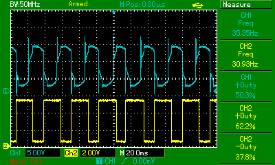
The delta values are analogous to the duty cycle. As mentioned above, it is not necessary for a pulse to have more than 1/2 of the time, approximately 50%. These values can vary depending on the motor's design. In Image 3, the maximum configured during the test was approximately 38%.
The function below is executed at each edge transition of the Hall sensor input, meaning when it moves from one pole to another:
void handleFeedbackInterrupt() {
  // update current phase
  setPhases();
  // calculate new pulse width
  unsigned long now = millis();
  pulseWidthMillis = calcultePulseWidth(phaseStartMillis, now, frequencyDelta);
  phaseStopMillis = phaseStartMillis;
  phaseStartMillis = now;
  // calculate new RPM
  rpm = calculateRPM(pulseWidthMillis, POLES);
}
It updates the following values:
Finally, we have the section that executes the calculated delay, simulating a PWM period. When the period ends, the signal is turned off:
// Using frequency delta control
    case STEP_FEEDBACK:
      {
        // Update feedback delta
        frequencyDelta = calculateFrequencyDelta(PIN_FREQUENCY);

        // Get timestamp
        unsigned long now = millis();

        // Performing delay
        if (now <= phaseStartMillis + pulseWidthMillis) {
          setOnOff(currentPhase, lastPhase, 1);
        } else {
          setOff(currentPhase);
        }

        break;
      }
The program can be simulated on Tinkercad.
In this simulation, the motor has been replaced with a frequency generator that alternates a signal as if it were the rotor spinning and generating a high and low signal on the Hall sensor. There is also control over the frequency delta using a potentiometer.
Below, we have images of the circuit in operation.
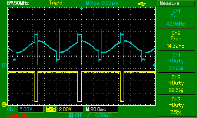
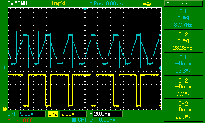
The yellow channel shows the PWM signal generated by the microcontroller. The "-Duty" value indicates the percentage of the signal that powers the coil.
The blue channel shows the angle and width where the pulse acts on the coil.
In this first image, the value is at its minimum:

In the second image, we have an intermediate value:

And finally, in the third image, at full power:

This technique, despite being very simple, has proven to be an interesting option for speed control.
Although the program's complexity is small, the fact that we have a microcontroller adds a potential point of failure to the system. With this technique, however, we only use a single sensor.
Using this technique, it is possible to make the push-pull topology "self-starting". In previous tests of this topology, even the use of two sensors did not guarantee this, as the rotor position can be in a blind spot.
We will explore more circuits with microcontrollers in future articles.
If you have any questions, feel free to contact me.