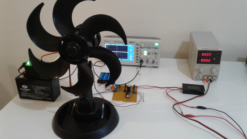
In today's article, we will see the first test with a new motor design.
This design has the following main objectives:
In a future article, I will share the 3D printing files of this new motor. I am still iterating on the design and making some adjustments.

Today, we will test a different topology from the previous ones. This topology has interesting characteristics:
The test setup consists of the motor and a 30 cm diameter propeller.
For this test, a 6-blade propeller will be used. This propeller can move more air and consequently has slightly higher electrical consumption compared to the 3-blade propeller used in previous tests.

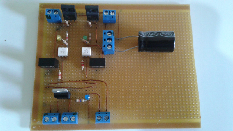
The circuit used in this test employs a push-pull topology.

The figure below depicts the control circuit. The switching sensor can be an optical sensor or a Hall sensor. For this test, we will use a Hall sensor.
In this topology, two sensors are required: one for each pulse direction.

The circuit works as follows:
Since C1 controls the charging and discharging of the pulse, its size determines the motor's power. However, it should be sized according to L1:
Electrical characteristics:
This motor was designed to operate with voltages between 9 and 36VDC (depending on the coil arrangement).
The results are shown for coil configurations in series and parallel.
Bifilar in series:
| Voltage (V) | Current (A) | Power (W) | Speed (rpm) |
|---|---|---|---|
| 12 | 0.06 | 0.7 | 440 |
| 18 | 0.1 | 1.8 | 628 |
| 24 | 0.14 | 3.3 | 800 |
| 32 | 0.21 | 6.7 | 1030 |
Capacitor(s) used: 1x 63V/1000uF.
Bifilar in parallel:
| Voltage (V) | Current (A) | Power (W) | Speed (rpm) |
|---|---|---|---|
| 9 | 0.19 | 1.7 | 600 |
| 12 | 0.27 | 3.3 | 746 |
| 18 | 0.44 | 7.9 | 1014 |
| 24 | 0.61 | 14.6 | 1220 |
Capacitor(s) used: 2x 63V/1000uF.
The results are quite satisfactory, especially considering the amount of wire used in the coils. Comparing with previous tests, there has been a reduction of approximately 35% in material.
The higher number of poles (6) makes the pulses shorter, reducing waste of charge in the coil.
The topology used also helps to minimize waste, although I have achieved similar results using a traditional H-bridge configuration.
Regarding the number of magnets used, there has also been a reduction of approximately 10% in the total weight.
If you have any questions, feel free to contact me.