This article is the first in a series of tests we will conduct to find possible alternatives for components and circuits for this version of the Keppe motor.
The main objective of this series is to simplify the design and potentially reduce costs in the construction of the motor.
The tests will be conducted with some possible circuit topologies and also with versions using different materials (copper and aluminum coils).
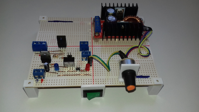
The prototype below has 3 main components:
This prototype was built in two versions, one with a copper coil and the other with an aluminum coil. The estimated costs were:
The components included in this cost estimate are:
The control circuit was not included in the final cost, but it may be relevant depending on the topology.
The value of the minimum wage in Brazil is R$ 1,320.00.
This test will evaluate whether this topology is reliable for use.
In pulsed motors, when the electrical power supply to the coil is turned off, there is a very high voltage spike, which can damage the electronic switch.
In MOSFETs, this risk is somewhat mitigated by the component itself, which has a reverse current diode in its construction. However, depending on the power to be dissipated, it is possible for the component to be permanently damaged.
If this voltage spike is not dissipated, it also generates an audible noise in the motor.
Normally, it is instructed to use the so-called flyback diode in parallel with the motor coil, which causes this spike to be dissipated in the coil itself. However, in pulsed motors (depending on the rotor configuration), the generating phase of the motor causes the coil to practically short-circuit in part of the rotation cycle, causing the motor to lose speed.
Another alternative is to place a certain capacitance in parallel with the coil, which attenuates the voltage spike. This is the solution we are going to test. The amount of capacitance will depend on the characteristics of the coil.
The MOSFET used in the test was the K2645.
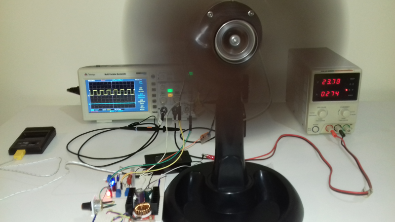
The test environment is composed of the motor and a 30cm diameter propeller.


Quick video showing the environment.
The development board contains:

The figure below shows the control circuit. The switching sensor can be an optical sensor or a hall sensor. For this test, we will use an optical sensor.

Electrical characteristics:
This motor was designed to work with voltages between 60 and 120VDC.
The test was executed from start to finish, meaning the motor was running continuously for 50 minutes.
Each result row was obtained with the motor running for 10 minutes.
The ambient temperature was constant, around 24.3°C.
| Voltage (V) | Current (A) | Power (W) | Temperature (°C) |
|---|---|---|---|
| 60 | 0.07 | 4.2 | 25.3 |
| 70 | 0.08 | 5.6 | 25.9 |
| 80 | 0.10 | 8.0 | 26.5 |
| 90 | 0.11 | 9.8 | 26.8 |
| 96.5 | 0.12 | 11.5 | 27.7 |
The rows below show the performance of the motor with this topology.
| Voltage (V) | Current (A) | Power (W) | Speed (rpm) |
|---|---|---|---|
| 60 | 0.07 | 4.2 | 852 |
| 70 | 0.08 | 5.6 | 975 |
| 80 | 0.10 | 8.0 | 1098 |
| 90 | 0.11 | 9.8 | 1194 |
| 96.5 | 0.12 | 11.5 | 1260 |
This simple topology proved to be reliable regarding the possible damage of the electronic switch due to overheating.
This topology has no safety mechanism against excess current, which is always desirable. This could be implemented with some type of passive component, such as a fuse, for example. In future tests, we can make some improvements.
The circuit is very simple and has few components, having fewer possible failure points.
It is worth mentioning that the tests were conducted at a power level below the maximum at which the motor can operate More tests at higher power levels and for longer periods of time should be more conclusive.
If you have any questions, feel free to contact me.